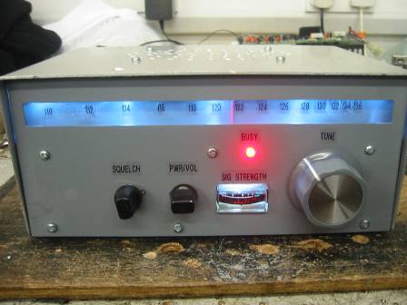
Described here is an airband receiver with good performance. All parts came from the junk box so there is plenty of scope for experimentation using alternate parts. After much experimenting, this is the final design. The set itself is a double conversion AM superhet which gives good selectivity and sensitivity and covers 110MHz to 136MHz. The first IF is 10.7MHz and the second IF is 455 KHz. The five gang tuning capacitor was salvaged from a scrap FM/AM tuner; the first two gangs of the FM section are used for preselector tuning while the last gang (the largest of the three FM sections) is used for local oscillator tuning.
Looking at the circuit diagram you will see that the antenna signal is fed to a low impedance tap on tuned circuit L1/C1. This circuit along with L2/C2 form a preselector to attenuate out of band signals. L1 and L2 are lightly mutually coupled and as a result give good preselector performance which is necessary to keep out strong image frequencies (FM broadcast stations). The coil formers for L1 and L2 were taken from the helical filter module of an old Europer PMR set, these were then rewound accordingly. Thick wire can be used so as to avoid having to use a former. L2 has a low impedance tap which gives a good match to the base of Tr1 which is configured as an RF amplifier. It is this stage that effectively determines the noise figure for the rest of the receiver; hence a low noise transistor is used here. R1 prevents any instability that otherwise may occur. Bias for Tr1 is provided by R2/R3. The collector load for Tr1 is untuned (R3) as this gave best results. C5 couples the amplified RF signal to the gate of the mixer Tr2 and provides DC blocking. Tr2 is a J-FET (2n3819) and has good signal performance (better than a bipolar transistor). The local oscillator is injected into the source of Tr2. The wanted IF signal (10.7 MHz in this case) as a result of mixing is “picked” out from the drain of Tr2 via IF transformer IFT1. The other frequencies present at Tr2 drain (F1, F2 and F1-F2) will be ignored by IFT1. The resulting IF signal is then fed to the IF amplifier module.

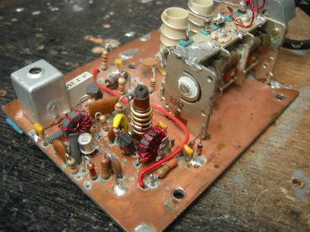
The local oscillator operates at 10.7 MHz above the wanted incoming signal frequency i.e. if the wanted frequency is 118 MHz, then the local oscillator frequency will be 128.7 MHz. High side oscillator injection was chosen because it aids the preselector effectiveness against strong broadcast FM stations. Tr4 (also a J-FET) along with L3/C8/C9 and associated components form a Hartley oscillator which provides a fairly constant output amplitude across its frequency range (120.7 MHz to 146.7 MHz). ZD1 stabilizes the supply to the oscillator which aids stability/ drift. The output of the oscillator is taken from a tap on L4 which is then fed to TR5 base via C13. Tr5 is connected as a buffer amplifier to raise the local oscillator level to approximately 500 mV peak to peak and also reduces oscillator pulling. C8 was introduced in series with the main tuning capacitor to reduce its maximum capacitance in order to achieve correct L/C ratio with L3 (remember this tuning cap was robbed from a broadcast tuner operating at a slightly lower frequency than is used here). A result of C8 is a slightly cramped tuning scale at the HF end; a better solution would be to remove some of the moving plates of the tuning capacitor to achieve correct capacitance and a linear scale. Plates were removed on the two preselector gangs, Maybe later I will do the same on the oscillator gang and have a nice linear scale. (I can’t remember why I didn’t do this, but I know there was a reason at the time – probably laziness!). Looking at photograph of the front end board shows the layout I used. You may notice some thin twisty bits of enamelled wire on top of the tuning capacitor. These are makeshift trimmer capacitors of a few pF in value to track the two tuned circuits – unusually there were no built in trimmers on the FM tuning capacitor sections. All screening cans and formers used in this project came from an ancient duff Westminster set.
The heart of this unit is a TDA1072A dedicated AM sub strip integrated circuit. It comprises of a mixer, IF amplifier, RSSI and demodulator, see manufacturers datasheet for details. This chip was taken from an 80’s car radio (most car radios of this vintage will have on of these), however it is still readily available to this day. Of all the modules in this project this one gave me the biggest head ache. The manufacturer claims a useable sensitivity of 1.5uV. Two different chips were tried and the best sensitivity attainable was 30uV!! A single stage amplifier had to be added ahead of the chip to achieve a suitable sensitivity. The main reason for using the chip is the RSSI output (received signal strength indication) to drive an S-meter and to run the squelch circuit. The other problem encountered was the second conversion mixer. The chip has an onboard mixer and oscillator which are used for the second conversion to an IF of 455 KHz in this project. According to the datasheet the oscillator will run up to 45Mhz with an external crystal, I tried three different crystal oscillator circuits using the chips internal oscillator but could not get it to run reliably. In the end a separate external oscillator was built and fed into the chip (hence the very small add on board mounted on the IF module – look for the crystal). Looking at the circuit diagram of the IF module you will see the incoming IF signal is passed through FL1, this is a 10.7MHz ceramic filter taken from the scrap tuner. You will also find these in CB sets and FM broadcast radios or they can be purchased new (sharp intake of breath!) from the usual suppliers. Although primarily designed for FM use they work well here. This filter gives the radio most of its selectivity and is good for 50 KHz channel separation. From the filter 10.7 MHz IF signal is amplified by J – FET Tr3 (another 2N3819 – you will find these in abundance inside old Europer PMR sets or you can buy new). IFT 2 is a 10.7 MHz IF transformer also taken from a tuner. The low impedance secondary winding is fed into IC 1 (TDA1072A) on pin 14. Second local oscillator signal (10.245 MHz) generated by Tr6 (a colpits crystal oscillator) is fed into pin 12. The crystal used in conjunction with Tr6 is a 10.245 MHz type used for second local oscillator in many different PMR sets, mine came from an old Storno ( Westminster’s use a 11.155 MHz type which is also suitable) These two signals are mixed together within the chip to produce the second IF of 455 KHz. This second IF leaves the chip on pin 1, passes through IFT 3 and renters on pins 3 and 4. A 455 KHz AM filter was originally fitted between IFT3 and pins 3/4 but was found unnecessary as there is sufficient selectivity given by FL1 and the IF transformers. The 455 KHz IF signal is AM demodulated in the chip, audio appearing on pin 6. A received signal strength indication voltage is output on pin 9 of the chip which is used to drive an S-meter and provide a sample voltage for the squelch circuit. The manufacturer’s datasheet is not very detailed and no chip internal circuit diagram is given. As a point of interest, it was found that there must be a DC path between pins 11 and 12 when using an external crystal oscillator hence the RFC. The AF signal is then fed to the squelch circuit and finally to the audio power amplifier.

The squelch module consists of discrete devices and performs well. Included in the squelch module is a simple S-meter which gives relative signal strength indication. Present on pin nine of the IF chip (TDA1072) is a voltage which varies from approximately 0.2 Volts for no signal up to approximately 2.6 volts for a signal of 300 uVolts into the receiver, it is called RSSI voltage ( received signal strength indication). This voltage drives the S-meter directly via a few passive components. The meter used here is from a CB set but any meter with a FSD of 50 – 200uA will be fine. R1 with Vr2 is used to zero the meter under no signal conditions whilst Vr1 is used to set the full scale deflection with maximum signal input. The RSSI voltage is used to control the squelch circuit operation. Tr1, 2 and 3 form a Schmitt trigger which monitors the incoming RSSI voltage set by Vr3 (the squelch control). When the RSSI voltage exceeds the threshold voltage of the Schmitt trigger (approximately 0.9 volts), Tr2 is biased off. This in turn causes Tr3 to conduct allowing 12 volts to be present at its emitter. With 12 volts present at the emitter of Tr3, DC supply to the audio power amplifier is maintained and also the squelch gate (Tr4) allows audio to pass. Tr4 is simply an emitter follower (a buffer), audio from the IF chip enters the buffer via C2 and leaves via C4 to the volume control. Squelched audio also passes through C3 which is connected to a phono socket on the rear of the chassis for external audio out (recording etc.). With no 12 Volts DC present at Tr3 emitter (i.e. no signal present) both the audio power amplifier and the buffer will not pass any audio thus eliminating the annoying hiss present with no received signal. If you are not bothered about an external audio feed then Tr4 and its associated components can be omitted as the audio power amplifier will still be “squelched”. Also included is a busy light consisting of an LED connected to Tr3’s emitter, when there is a signal present or if the squelch is opened via the squelch control the LED will light accordingly. For such a simple circuit it really does perform well, you could use a more elaborate circuit with better performance but I don’t think it is justified in this project. All of the transistors used are BC108’s (Europa again!), however any general purpose npn small signal transistor will do (BC546 etc.)
As you can see from the circuit diagram, the audio power amplifier is made from discrete components and is shown for interest only. The only reason this was done is because at the time of building/designing I had no LM386’s in the junk box. This discrete amplifier is not to be recommended as the LM386 is superior in every way and as such an alternative circuit is also given. Old timers will probably recognise the discrete transformer coupled amplifier circuit (most 70’s pocket radios had something similar to this in them), I had the bits in the junk box so I used them. Power output is a few hundred milliwatts which is fine for most purposes. As can be seen, the LM386 amplifier is very simple and low component count. Audio enters via pin three and exits at speaker level from pin five, a Zobel network is included on the output, not much to say really! A more powerful amplifier chip could be used if so desired, however Tr3 in the squelch circuit would have to be changed to a power Darlington pair due to the increased current demand from the more powerful amplifier.
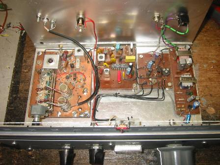
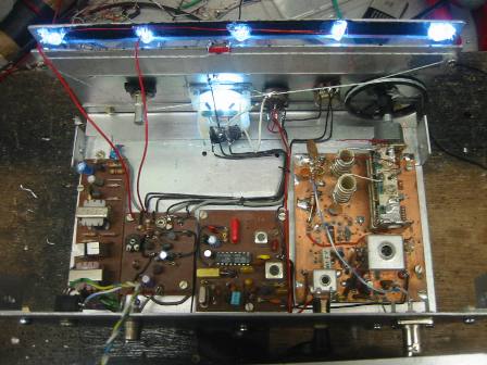
The radio is built in modular form as this allows each module to be built and tested individually. The RF board is probably the most difficult to construct and very much depends on what type of tuning capacitor you may have, my layout suites the capacitor I had at the time. A printed circuit board is recommended for this module. Keep all wiring/PCB tracks as short as possible; remember this is VHF and not so forgiving as HF regarding lead lengths etc. As far as mechanical construction goes that is very much up to the individual constructor. I used a drive cord (braided Dacron fishing line) tuning scale purely for simplicity, if you’re not bothered about absolute frequency readout then a reduction vernier would be okay, there are many possibilities. Photograph four gives a view of the drive cord arrangement used in this project and photograph five shows the scale lamps, I used five white high brightness LED’s running with less than the usual current flowing through them (these are running with 15 mA) as this greatly prolongs their life. Epoxy glue was used to stick the LED’s in place. The optional RF preamplifier can also be seen on the RF board, built dead bug style next to L1. An old germanium transistor is used in this preamp (and it is a PNP type) as several were in the junk box, however a modern silicon transistor can also be used provided the base bias resistor is changed accordingly (see table in circuit diagram). The preamp is configured as a grounded base amplifier (or common base as it is also known). Housing all of the modules in a screened metal cabinet is recommended although a wooden cabinet lined with aluminium foil can be used. A suitable loudspeaker is mounted in the lid of the case.

The RF and IF boards are the only modules requiring alignment. The following procedure assumes the squelch and IF boards are connected correctly together. Set Vr1 on the squelch board to 3/4 of its travel (i.e. it is about 10k). Next adjust Vr2 so the meter indicates 2 to 3 on the scale. Inject a 10.7MHz signal at 10mV pk-pk (unmodulated is fine) into the input of the IF board. Adjust IFT1 and 2 for maximum indication on the S-meter. If you exceed meter FSD then reduce signal generator amplitude and readjust Vr1. If you don’t have a signal generator then all is not lost; if the transformers came out of working sets or sets that have not been tweaked then they will not need much alignment and can be set up once the RF board has been adjusted (my transformers only needed an1/8 of a turn tweak). Also, I think the club has a signal generator that could be used. The alignment of the RF board does require a frequency counter capable of reading up to 150 MHz. Connect counter to Tr2 source. Adjust L3 to obtain a frequency range of 120.7 MHz to 146.7 MHz from end to end of tuning capacitor. The next step assumes RF module is connected to IF module correctly and rest of boards are connected and working correctly. Set squelch so busy LED lights. Inject an AM modulated signal of 300uV @ 120 MHz into antenna socket. Tune into signal using tuning capacitor. When signal is heard adjust trimmer capacitors on C1 and C2 (assuming they are physically there) for maximum signal strength. Adjust T1 for maximum signal. Readjust IFT1 and 2 on IF board for maximum signal strength. Readjust trimmer capacitors on C1 and 2 for best band edge strength (high and low). If you do not have a signal generator, connect antenna to radio and tune for one of the many constant data channels present in the airband (start with one in the middle of the band if possible) and align as above.
Once alignment is complete you will have a good airband receiver. As it is, sensitivity will be good for modulated signals of 3uV or better. If you are in a fringe area of the airport then you can add the optional RF preamplifier which will increase the sensitivity to 0.5 uV. If you are within 30 miles of an airport then you will hear sky born traffic easily without the need for the preamplifier but to hear the tower you will probably need the preamplifier unless you have a good antenna (all I have is 2m of wire poking out the back of the radio in my attic).
Optional RF pre-amp circuit diagramL1 and L2 - 5 turns on 10mm former, air cored. L1 tap at ¾ turn from cold end (ground end). L2 tap at ½ from cold end. Space wound and occupies all of former length (25mm). IFT1 – 25 turns 32swg enamelled Cu on 5mm IF former. Tap at 7 turns from cold end (HT end). Slug tuned. L3 – 5 turns 18 swg enamelled Cu on 5mm IF former space wound and slug tuned, tap at 2 turns from cold end. L4 and L5 – 10 turns 32 swg enamelled Cu bifilar wound on Amidon FT50-43 torroid core. All IF coil formers taken from old PMR sets (Westminster/Europer).
Tr1 – BFR91, Tr2, 4 – 2N3819, Tr5 BSX20. Tr2, 3, 4 and 5 can be found in Europa PMR sets.
IFT 2 – standard 10.7 MHz IF transformer (CB sets etc.), IFT3 – standard 455KHz IF transformer (CB sets)
Misc. Xtal 1 – 10.245 MHz second conversion crystal (11.155 MHz also ok) found in various PMR sets. FL1 – 10.7 MHz ceramic filter (tuners, FM radios, CB sets)
IC1 TDA1072A, Tr3 – 2N3819, Tr6 – BC108 (lots in Europa).
Barry Zarucki M0DGQ HOME